






Dedicated to precisely empowering industrial security

Fire Alarm Control Panel for Energy Storage Power Stations
Keywords:
Fire Alarm Control Panel for Energy Storage Power Stations
Product accessories:
Detailed Introduction

The HB-FGS-1500 fire alarm control panel for energy storage power stations (hereinafter referred to as HB-FGS-1500) is a product specifically designed for industrial applications. It can connect multiple combustible gas detectors and simultaneously display the combustible gas concentrations in the areas monitored by these detectors. When the combustible gas concentration in any protected area exceeds the preset alarm threshold, the controller will activate an audible and visual alarm, indicating the alarmed zone and the corresponding concentration at the time of the alarm, while continuing to monitor the dynamic changes in gas concentration within that zone. This controller can accommodate both one-channel bus-type detectors and four-channel 4–20 mA point-type detectors.
The HB-FGS-1500 is equipped with a 320×240 dot-matrix TFT LCD display, which, under normal operating conditions, provides real-time indication of the combustible gas concentration in each zone; in alarm mode, it displays the alarm address and alarm level; and in fault mode, it indicates the type of fault and the location where the fault occurred.
The HB-FGS-1500 is a fire alarm control panel for energy storage power stations, designed in accordance with the national standard GB 16808-2008, “Fire Alarm Control Panels for Energy Storage Power Stations.”
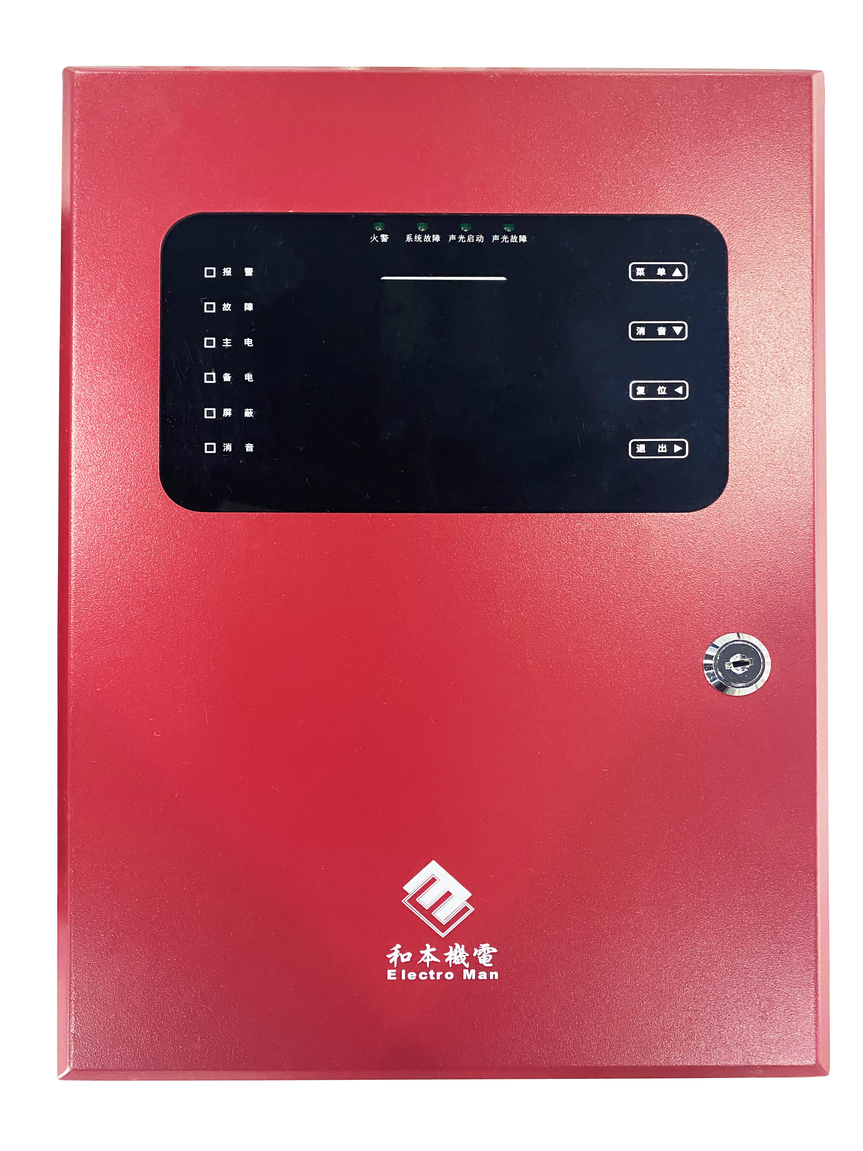

- The controller interfaces with intelligent smoke detectors, heat detectors, manual fire alarm push buttons, and audible–visual alarms to enable fire detection and alarm notification.
- The gas fire suppression system is activated and discharged through interlock with the controller’s emergency start button, on-site emergency start buttons, fire detectors, and manual fire alarm push buttons.
- Upon receiving the start control signal, the controller shall activate the on-site zone alarm to sound an alarm simultaneously, automatically display the delay time and indicate the duration of the delay, and interlock with the output module to perform functions such as closing doors and windows, actuating fire dampers, and shutting down the air-conditioning system.
- During the start-up delay period, the emergency stop function for subsequent gas fire suppression operations can be activated via the controller’s emergency stop button, the on-site emergency stop button, or the controller’s reset button.
- The controller features both automatic and manual operating modes. In automatic mode, fire alarm linkage can be used to initiate gas extinguishing; in manual mode, activation can only be achieved via the controller’s emergency start button or the on-site emergency start button.
- The controller is equipped with system networking capabilities, enabling networked communication with the fire alarm linkage control panel for remote monitoring.
- Strong historical event logging capability, with the capacity to record up to 28,000 events, including 7,000 fire alarm records, 7,000 interlock records, and 7,000 other event records.
- The color LCD display features a window-based menu interface, real-time information categorization, and priority-based display, with convenient navigation via function keys and arrow keys. If no operations are performed within the set time period and no new events occur, the screen will enter power-saving mode. When an event or operation is detected, the LCD screen automatically illuminates.
- The controller features manual and automatic login as well as offline collaborative programming, enhancing construction efficiency and accuracy.
- The polarity-free two-bus design simplifies and enhances the flexibility of system cabling while improving wiring reliability.
- It features built-in backup power and automatically switches to backup mode when the main power supply is unavailable. With a sophisticated power-management design, it ensures fast and reliable charging of the backup battery throughout the entire utility-grid operating voltage range. During backup operation, it includes undervoltage protection: when the backup battery voltage drops below DC 21 V, the power supply will automatically shut off.

Name | Parameters |
Installation Method | Wall-mounted |
Main Power | AC 220V ±10% / 50Hz |
Backup power | 2 × DC 12V/1.3Ah lead-acid batteries |
Fuse Rating (Main Power) | 1A/250V |
Fuse Rating (Backup Power) | 5A/250V |
Equipment Capacity | One bus-based loop, with two detectors connected per loop. Four branched-loop circuits, with one detector connected to each circuit. |
Communication Methods | Modbus RTU (RS485) |
Alarm Setting | Two alarm levels (low alarm, high alarm) |
Alarm Output | Two-channel passive normally open contact output, with a contact rating of AC 125 V/0.5 A and DC 30 V/1 A. |
Display method | 2.8-inch TFT Chinese display |
Programming method | Button |
Alarm Method | Audio-visual alarm |
Alarm sounds | Two audible signals—alarm and fault—75–110 dB at 1 meter directly in front |
Indicator light | Alarm: Red, Fault: Yellow, Main Power: Green Standby power: green; Shielding: yellow; Mute: green |
History Records | 1,000 alarm event records, 500 fault event records, and 500 other event records. |
Operating temperature | 0°C to 40°C |
Operating humidity | 10–95% RH (no condensation) |
Work stress | 86~106 kPa |
Main Material | Cold-rolled steel sheet with powder coating on the surface |
Application Scenarios
Project
Navigation
Contact Us
Address: 2nd Floor, Building F, No. 21 Software Avenue, Yuhuatai District, Nanjing
Copyright © 2024 Nanjing Heben Mechanical & Electrical Equipment Technology Co., Ltd. Technical Support:China Enterprise Dynamics Nanjing Digital Business Card