


Committed to precision empowerment industry safety

Fire alarm control device for energy storage power stations
Key words:
Fire alarm control device for energy storage power stations
Case Details
Product Introduction:
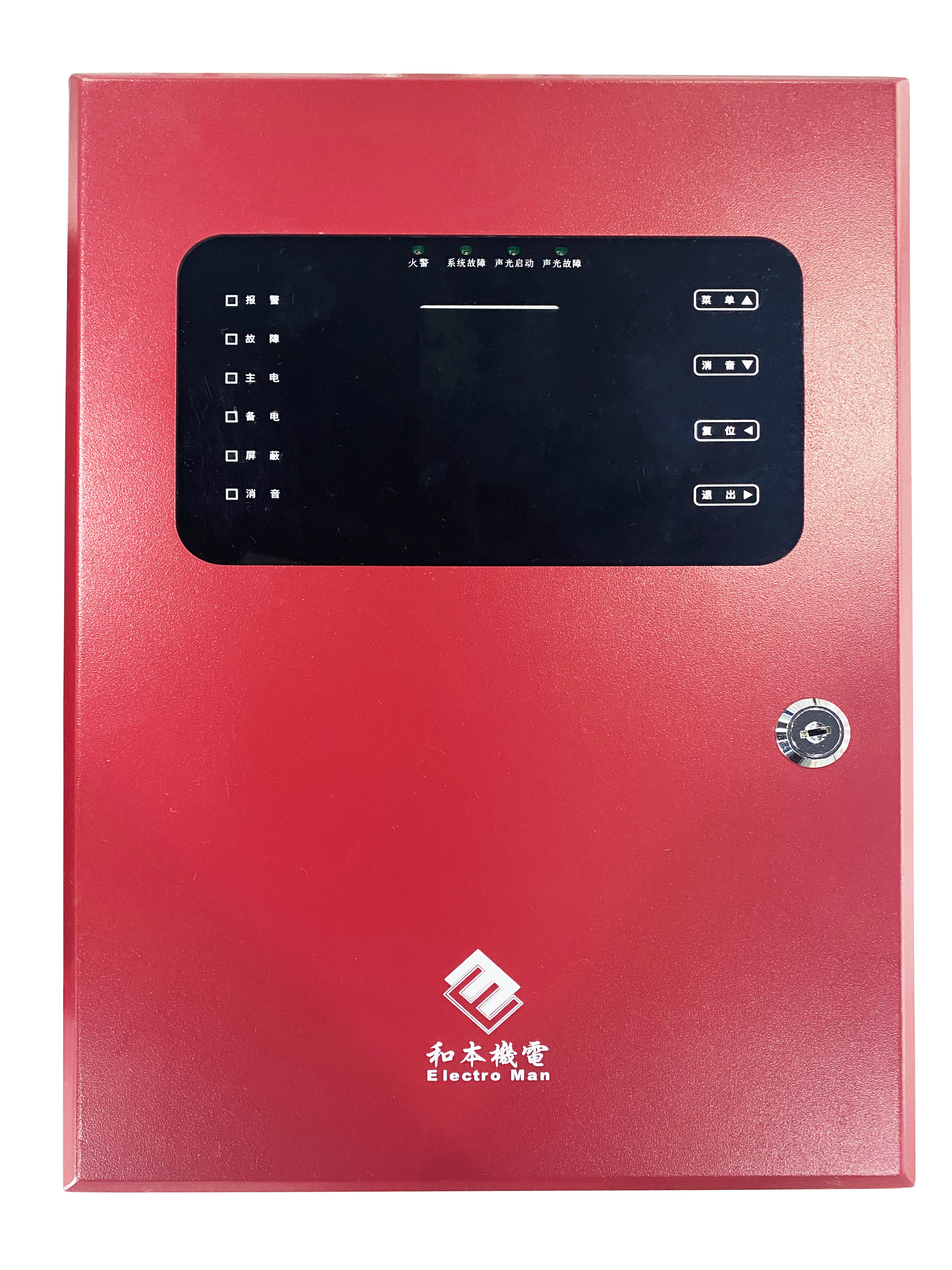
The HB-FGS-1500 fire alarm control device for energy storage power stations (hereinafter referred to as HB-FGS-1500) is a product specifically designed for industrial sites. It can connect multiple combustible gas detectors and simultaneously display the concentration of combustible gas in the areas where the detectors are located. When the concentration of combustible gas in any protected area exceeds the set alarm threshold, the controller can issue corresponding audible and visual alarm signals, indicating the alarm area and the concentration at the time of the alarm, while continuing to monitor the dynamic gas concentration in the alarm area. This controller can simultaneously connect to 1 channel of bus-type detectors and 4 channels of 4-20mA branch-type probes.
The HB-FGS-1500 is equipped with a 320×240 dot matrix TFT LCD indicator, which displays the concentration of combustible gas in each area in real-time under normal conditions; during an alarm state, it shows the alarm address and alarm level; in a fault state, it can display the type of fault and the location of the fault.
The HB-FGS-1500 is designed according to the national standard GB 16808-2008 "Fire Alarm Control Device for Energy Storage Power Stations."
Features:
- The controller connects to intelligent smoke, temperature detectors, manual fire alarm buttons, and audible-visual alarm devices to achieve fire detection and alarm.
- By linking the controller's emergency start button, on-site emergency start button, fire detectors, and manual fire alarm buttons, it can initiate the spraying of gas extinguishing equipment.
- After receiving the start control signal, the controller can activate the area alarm devices on-site simultaneously, display the delay automatically, indicate the delay time, and link to start the output module to close doors and windows, fire dampers, and stop air conditioning.
- During the start delay period, the emergency stop button on the controller, the on-site emergency stop button, and the controller reset button can be used to implement the emergency stop function for gas extinguishing.
- The controller has both automatic and manual working modes. In automatic mode, it can achieve fire alarm linkage to start gas extinguishing; in manual mode, it can only be started through the controller's emergency start button or the on-site emergency start button.
- The controller has a system networking function, allowing it to communicate with fire control linkage controllers for remote monitoring.
- It has a strong historical event recording capability, capable of recording up to 28,000 historical events, including 7,000 fire alarm records, 7,000 linkage records, and 7,000 fault records, along with 7,000 records of other events.
- The color LCD display uses a window menu-style working method, categorizing real-time information and displaying priority. It is easy to query using function keys and arrow keys. If no operations occur within a set time and no new events happen, it will enter screen saver mode. When an event/operation occurs, the LCD screen will automatically light up.
- The controller has manual, automatic login, and offline linkage programming functions, improving construction efficiency and accuracy.
- The non-polar two-bus design makes system wiring simple and flexible while improving wiring reliability.
- It has a built-in backup power supply that can automatically switch to backup operation mode when the main power is lost. It uses a comprehensive power management design to ensure quick and reliable charging of the backup power within the municipal power working range. The backup power has a low voltage protection function, automatically disconnecting the power when the backup voltage drops below DC21V.
Model Specifications:
Name |
Parameters |
Installation Method |
Wall-mounted |
Main Power Supply |
AC220V±10%/50Hz |
Backup Power Supply |
2×DC12V/1.3Ah lead-acid battery |
Fuse Capacity (Main Power) |
1A/250V |
Fuse Capacity (Backup Power) |
5A/250V |
Device Capacity |
1 bus circuit, connecting 2 detectors per circuit 4 branch circuits, connecting 1 detector per circuit |
Communication Method |
Modbus RTU (RS485) |
Alarm Settings |
Two-stage alarm (low alarm, high alarm) |
Alarm Output |
2 normally open passive contact outputs, contact capacity AC125V/0.5A DC30V/1A |
Display Method |
2.8-inch TFT Chinese display |
Programming Method |
Keypad |
Alarm Method |
Audible and visual alarm |
Alarm Sound |
Two sounds for alarm and fault, 75~110dB at 1 meter in front |
Indicator Light |
Alarm: Red, Fault: Yellow, Main Power: Green Backup Power: Green, Shielding: Yellow, Mute: Green |
Historical Records |
1,000 alarm event records, 500 fault event records, 500 other event records |
Operating Temperature |
0℃~40℃ |
Operating Humidity |
10~95%RH (no condensation) |
Operating Pressure |
86~106Kpa |
Main Material |
Cold-rolled steel plate, surface spray-coated |
Application Scenarios
Project
Navigation
Contact Us
Address: 2/F, Block F, No.21 Software Avenue, Yuhuatai District, Nanjing