


Committed to precision empowerment industry safety

Fire Alarm Controller/Gas Fire Extinguishing Controller
Key words:
Fire Alarm Controller/Gas Fire Extinguishing Controller
Classification:
Case Details
Product Introduction:
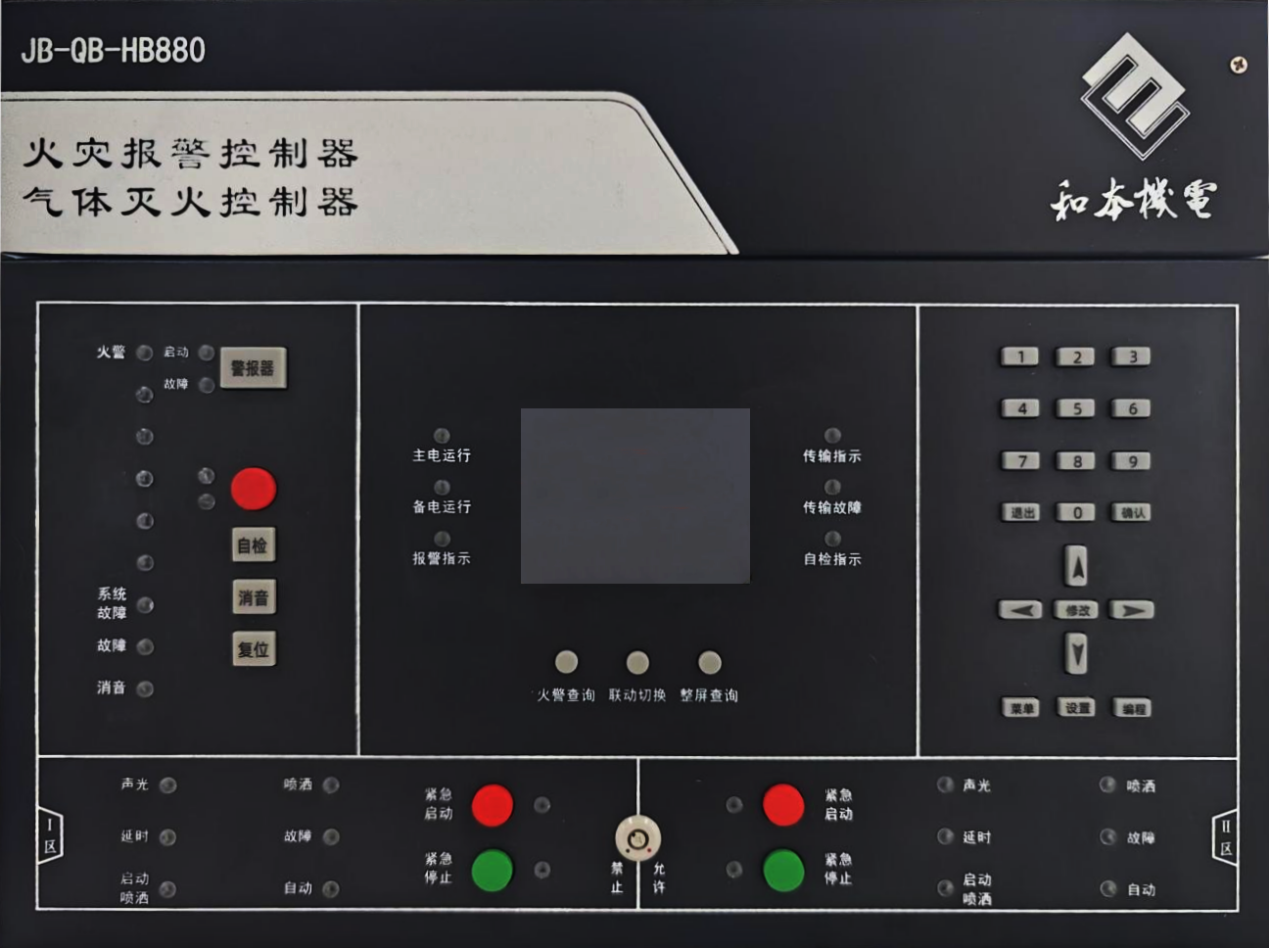
The JB-QB-HB880 fire alarm controller/gas extinguishing controller (hereinafter referred to as the controller) is designed by Nanjing Heben Electric Equipment Technology Co., Ltd. in accordance with national standards GB4717-2005 and GB16806-2006, combined with practical engineering conditions. It is equipped with 1 or 2 gas extinguishing zones, along with detectors, manual alarm buttons, sound and light alarms, and other related peripherals, forming a dual-function fire alarm controller and bus gas extinguishing controller. The system is stable and reliable, and can be widely used in fire alarm and gas extinguishing systems in various fields.
Features:
- The controller connects to intelligent smoke, temperature detectors, manual fire alarm buttons, and sound and light alarms to achieve fire detection and alarm.
- By linking the controller's emergency start button, on-site emergency start button, fire detectors, and manual fire alarm buttons, it can initiate the gas extinguishing equipment's spraying.
- After receiving the start control signal, the controller can activate the local area alarm while sounding the alarm, automatically display the delay and indicate the delay time, and link to start the output module to close doors and windows, fire dampers, and stop air conditioning.
- During the start delay period, the controller's emergency stop button, on-site emergency stop button, and controller reset button can be used to achieve the emergency stop function for gas extinguishing.
- The controller has both automatic and manual working modes. In automatic mode, it can achieve fire alarm linkage to start gas extinguishing; in manual mode, it can only be started through the controller's emergency start button or the on-site emergency start button.
- The controller has a system networking function, allowing it to communicate with fire linkage controllers for remote monitoring.
- It has a strong historical event recording capability, capable of recording up to 28,000 historical events, including 7,000 fire alarm records, 7,000 linkage records, and 7,000 other event records.
- The color LCD display uses a window menu working method, categorizing real-time information and displaying priority. It is easy to query using function keys and arrow keys. If no operations occur within a set time and no new events happen, it will enter screen saver mode. When an event/operation occurs, the LCD screen will automatically light up.
- The controller has manual, automatic login, and offline linkage programming functions, improving construction efficiency and accuracy.
- The non-polar two-bus design makes system wiring simple and flexible while improving wiring reliability.
- It has a built-in backup power supply that can automatically switch to backup operation mode when the main power is lost. With a comprehensive power management design, it can quickly and reliably charge the backup power within the municipal power working range. The backup power has a low voltage protection function, which will cut off the power when the backup voltage is below DC21V.Cut off.
Model Specifications:
Name |
Parameters |
Operating Temperature Range |
-10℃~50℃ |
Operating Humidity Range |
Relative humidity ≤ 95%, no condensation |
Main Power |
AC187V ~ AC242V, 50/60Hz |
Backup Power |
2 DC12V/4.5Ah sealed lead-acid batteries |
Power Consumption |
Normal monitoring state ≤ 20W; maximum power consumption ≤ 50W |
Battery Charging Current |
400mA~600mA |
24V Power Output |
2 channels, DC24V/1A, resettable |
Solenoid Valve Drive Output |
2 channels, DC24V/3A, pulse mode/continuous mode, adjustable |
Spray Feedback Signal Input |
2 channels, dry contact input |
Loop Output |
2 channels, DC24V/300mA, pulse output |
Fire Alarm/Fault Passive Output |
Contact capacity DC30V/3A |
Dimensions (mm) |
Length 405mm × Width 295mm × Thickness 100mm |
Weight |
Approximately 7Kg (including battery) |
Shell Protection Level |
IP30 |
Installation Method |
Wall-mounted, supports top entry and rear entry |
Complies with Standards |
GB 4717-2005; GB 16806-2006 |
Application Scenarios
Project
Navigation
Contact Us
Address: 2/F, Block F, No.21 Software Avenue, Yuhuatai District, Nanjing